

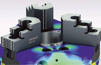
Schunk‘s wedge hook power chuck ROTA NCE combines lightweight construction, maximum load capacity and innovative design. The lathe chuck was geometrically adapted to the power flow for providing maximum stiffness as well as lightweight requirements. Compared to conventional lathe chucks and depending on the size, the mass inertia could be reduced by up to 40 per cent.
High Stiffness at Low Mass
The aim of the specialists at Schunk competence center for turning technology and stationary workholding in Mengen was the improvement of the energy management in accordance with DIN EN ISO 50001. They wanted to develop a clamping device with low mass or mass inertia in order to minimize the energy and duration required for acceleration. However, the basic clamping function of the chuck - measured in terms of stiffness and variability - should be fully maintained, if possible even increased. Also the desired radial and axial run-out accuracy had to be guaranteed.
In this case, the rough structure of the clamping device components was determined with topology optimization on the basis of the respective force flow. Using the resulting parameter optimization, dimensions were then varied to identify an optimal geometrical structure. For final optimization, e.g. of the jaw guidance, a suitable geometric parameterization is important, since the topology optimization does not allow a detailed depiction of the contact areas. In parameter optimization, lift-off and non-linear contacts of the entire chuck assembly can also be modelled and simulated. The properties of the optimized clamping device could be subsequently evaluated by FE analyses and compared with the previously manufactured designs.
Arched Structures below the Jaws
"In ANSYS, we defined an initial model for topology optimization including the necessary constraints such as forces and bearings," explains Mathias Siber, who used the project for his master's thesis. "The objective function of the optimization was the maximization of the stiffness, with mass restriction at 70, 50, and 30 percent of the initial mass." In addition, the existing functional areas were marked to exclude them from optimization (non-design areas) because they should remain in their original shape. The optimization algorithm then determined the basic geometrical shape according to the mechanical loads and specified mass restrictions. In the chuck body, arched structures below the jaw guide, circular recesses between the guideways and an overall conical chuck contour were created.
"The topology optimization significantly reduced the weight of the lathe chuck, which also has a positive effect regarding the load on the spindle bearings", stated Philipp Schräder, Head of Development Clamping Technology. "In addition, we registered the vault structure resulting from the topology optimization as a design patent at the German Patent and Trademark Office in order to protect it as far as possible from unauthorized copying."
Sensitivity Studies Show Influence Of Parameters
After topology optimization, parameter optimization was performed on the reconstructed parametric geometry model using sensitivity studies conducted with optiSLang from Dynardo. Thus, the influence of input parameters on the desired output data could be investigated, visualized and evaluated. The subsequently used optimization algorithm searched for the minimum of the correspondingly defined target function, including the reduction of lifting even at high clamping forces. In addition to the chuck body, base and top jaws were also included in the procedure.
"Using optiSLang we could fi gure out how the jaw guidance should look like", Mathias Siber explains. "We analysed which parameter changes would lead to the desired result of little deformation at low weight." Regarding the base jaw, mass and axial lifting were critical. Here, the parameters "depth of the guidance in the chuck body" and "width of the guidance groove" dominated. The depth of the guidance showed opposite effects, because the deeper the guidance in the chuck body, the lower the lifting effect. On the other hand, the mass of the base jaw increases proportionally.
Multi-Objective Optimization Facilitates the Design Process
In this case, parameters are optimized towards the objective of less lifting at the lowest base jaw mass. The result of this multi-objective optimization is an optimal depth width ratio of 2:3 for the base jaw guidance. This allows a very precise examination of the product behavior with different geometries in order to create a "robust" design. The robustness of the final design was ensured by means of suitable constraints.
While the topology optimization identified the lightest chuck design from the force flow, the parameter optimization ensured maximum stiffness and reduced notch stresses for the longest possible chuck life. In addition, a numerical stress analysis was conducted according to FKM guidelines.
The Prototype Meets All Requirements after optimization, prototypes of each chuck size were produced. Afterwards, they were examined and verified on a test bench with up to 500,000 cycles, which took several months. "Similar to other projects and due to the profound simulation during development, only one prototype per size was required to fully meet the specified requirements", emphasizes Philipp Schräder. "Since a prototype test can take several months, for a new development the time saved by the simulation is approximately half a year."
Topology and parameter optimization made a lightweight chuck possible where the mass was reduced by 30 per cent and the mass inertia by 40 percent. A 20 percent lower jaw centrifugal mass caused advantages such as shorter acceleration phases and a lower loss in clamping force under rotational speed. By optimizing the parameters in the jaw guidance area, the chuck stiffness was increased while the stress level was reduced at the same time. The result was a 20 percent increase of the maximum bearable clamping force. In combination with the reduced jaw centrifugal mass, a possible speed increase of 10 percent could be achieved. By reducing the time for testing combined with a stress calculation according to the FKM guideline and depending on the sizes, a cost reduction of approx. 30% could be reached in the development. As a result, the Schunk ROTA NCE lathe chuck provides the user with ideal conditions for high process dynamics and productivity while using a minimum of energy. Particularly in large-scale production, the energy- and cycle-time efficiency of the chuck leads to significant savings and fulfills the DIN EN ISO 50001 energy management certification.
Source: Schunk GmbH & Co. KG
END