


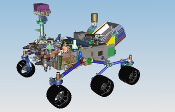
Rover Deployed Side - CAD
Complex design
Very rarely are the products used in these critical deployments simple. Items such as satellites, spacecraft, deep water submersibles and high-end research equipment are generally very intricate designs. Each item is often a one-of-a-kind product, which must be designed from scratch, for both digital simulation and mechanical construction.
Thousands of these discreet components combine in a single unit, every one of which must be able to operate flawlessly within certain tolerances and must remain in alignment with each other.
Because there will be only one opportunity for these projects to succeed, every part and assembly of every system needs to be thoroughly tested to ensure that all instruments will function flawlessly under expected conditions.
As such, engineers need to be able better understand loading conditions throughout these complex products. They must be able to take a structure, run the analysis and see what breaks.
More specifically, designers should be able to import geometry from any 3D format, helping quickly switch from a virtual prototype to the FE model with a consistently accurate import process. Here, the virtual prototype stage is vital for structural and thermal analysis as well as digital simulation.
Combining CAE solvers in conjunction with the right tools, engineers can conduct simulations to ensure each part does not interfere with another and that parts and assemblies have sufficient strength to withstand extreme temperature variations and vibrations under load and during normal operating conditions.
New materials
The use of composite materials in designs has increased significantly in recent years. These can be particularly in these critical, bespoke designs where more exotic combinations might be required to offer protection from the harsh elements.
Being able to run simulations and testing that account for the specific properties of these composite structures is crucial to fully realising the success of mission critical projects.
Simulation can help model and post-process results on composite structures. Furthermore, with a laminate editor and viewer, it's possible to update the laminate properties interactively while creating and modifying plies in the laminate.
A visual approach
When dealing with complex, mission critical designs, being able to visualise the results is an increasingly crucial element to solve any analysis issue quickly and effectively. It enables engineers to find where the breaking points are and how the design reacts to temperature and pressures.
Engineers can easily understand the mathematical results of an analysis conducted with a solver, but visualising analysis results using Femap shows exactly what is going on. As such, visualisation in post-processing is a key advantage. Visualisation is key to being able to view and interpret the output data including offering contour and criteria plots, deformed shape animations, time and frequency domain animations as well as dynamic cutting plane and iso-surfaces.
With a wealth of visualisation capabilities at hand, engineers can view and interpret the results to quickly understand the model behaviour. To be fully effective in complex designs, this needs to include intricate design features such as beam modelling and meshing.
Model visualisation is also key to beam modelling. Users can view these elements as solid components and include offsets as well as display options including shear and bending moment diagrams.
(Continued on the next page)